Brake Systems
Dual Air Brake System
A dual air brake system consists of two independent air brake systems that use a single set of brake controls. Each system has its own reservoir, plumbing, and brake chambers. The primary air system operates the service brakes on the rear axle; the secondary air system operates the service brakes on the front axle.
Primary Air Brake System
Loss of air pressure in the primary air system causes the rear service brakes to become inoperative. The front brakes will continue to be operated by the secondary air system.
Secondary Air Brake System
Loss of air pressure in the secondary air system causes the front axle brakes to become inoperative. The rear service brakes will continue to be operated by the primary air system.
Emergency Braking System
When air pressure is lost in one air system, the air compressor will operate, but the air supply in the leaking system will not be replenished. There will be enough air in the working system to stop the vehicle safely. The dual air brake system thus provides emergency braking capability. When the low air pressure warning light and emergency buzzer first come on, stop the vehicle immediately. Do not drive the vehicle until the cause of the problem is corrected.
Parking Brakes
Pulling out the yellow diamond-shaped knob (parking brake control valve) on the auxiliary dash panel applies the parking brakes (spring brakes). See Fig. 12.1 for the standard parking brake control valve and Fig. 12.2 for the Intellipark™ parking brake control valve.
NOTE: If either control valve does not apply the parking brakes, the driver can manually set the parking brakes one of two ways:
With the ignition in the OFF position, pump the brakes to lower the air pressure in the system.
If the vehicle is equipped with a dump switch, turn the ignition to the ON position and press the dump switch to lower the air pressure in the system.
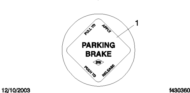
- 1. Parking Brake Control Valve
Fig. 12.1, Parking Brake Control Valve
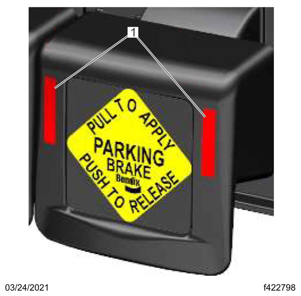
- 1. Light Emitting Diode
Fig. 12.2, Intellipark Parking Brake Control Valve
Air Brake Operation
WARNING
Before driving the vehicle, secure all loose items in the bus so that they will not fly forward during a full brake application.
Parking Brake Interlock, Optional
NOTICE
The service brakes and parking brakes have a safety interlock that prevents the unintentional release of the parking brake. These instructions need to be followed for the appropriately equipped vehicle to release the parking brake interlock.
Parking Brake Interlock Release
1.
Depress the brake pedal.
2.
Push the parking brake control valve in.
Parking Brake and Ignition Key Release
1.
Turn the ignition key to the ON position.
2.
Depress the brake pedal.
3.
Push the parking brake control valve in.
Parking Brake, Ignition Key, Wheel Chair Lift Interlock Release
1.
Turn the ignition key to the ON position.
2.
Check to see that the wheel chair lift is in the stowed position.
3.
Confirm that the wheel chair lift switch is in the OFF position.
4.
Depress the brake pedal.
5.
Push the parking brake control valve in.
Intellipark Parking Brake and Ignition Key Release
1.
Turn the ignition key to the ON position.
2.
Depress the brake pedal.
3.
Push the parking brake control valve in.
Intellipark Parking Brake, Ignition Key, Wheel Chair Lift Interlock Release
1.
Turn the ignition key to the ON position.
2.
Check to see that the wheel chair lift is in the stowed position.
3.
Confirm that the wheel chair lift door is closed.
4.
Confirm that the wheel chair lift switch is in the OFF position.
5.
Depress the brake pedal.
6.
Push the Intellipark parking brake control valve in.
Transmission Shifter Interlock Release
1.
If the vehicle is equipped with a wheel chair lift, make sure the lift is in the stowed position, and that the wheel chair lift switch is in the OFF position.
2.
Depress the service brake pedal to move the vehicle shifter out of the park position.
Operating the Brakes
To ensure safe operation and minimum brake wear, follow the steps below when operating the brakes.
1.
When the ignition switch is turned on, the low air pressure warning light (pressure circle icon) illuminates and the emergency buzzer sounds.
1.1
Monitor the air pressure system by observing the low air pressure warning light, the emergency buzzer, and both the primary and secondary air pressure gauges.
1.2
The warning light and buzzer shut off when air pressure in both systems reaches 65 to 75 psi (448 to 517 kPa).
2.
Before driving the vehicle, continue to monitor the air pressure system until the air compressor has built up a minimum pressure of 95 psi (655 kPa) in both the primary and secondary air systems.
3.
While driving, the low air pressure warning light and buzzer come on if air pressure drops below 65 to 75 psi (448 to 517 kPa) in either system.
3.1
If this happens, check the air system pressure gauges to determine which system has low air pressure.
3.2
Although vehicle speed can be reduced using the service brake, either the front or rear service brakes will not be operating, causing a longer stopping distance.
3.3
Bring the vehicle to a safe stop and have the air system repaired before continuing.
4.
During normal brake stops, depress the service brake until braking action slows down the vehicle. Increase or decrease the pressure on the pedal so that the vehicle comes to a smooth, safe stop.
IMPORTANT: In the event of a total loss of service brakes, use the parking brake control valve to bring the vehicle to a complete stop in the safest location possible.
5.
When the forward speed of the vehicle has decreased almost to the idling speed of the engine, shift the transmission to neutral. Apply the parking brakes, if the vehicle is to be parked.
NOTICE
Caging the Parking Brakes
WARNING
To move a vehicle with insufficient system air pressure, it is necessary to release the parking brake springs. Do this by caging (manually releasing) the parking brakes.
IMPORTANT: Before caging the parking brakes, make the connection to a towing vehicle or chock the tires.
After correcting the brake system problem, uncage the parking brakes before resuming normal vehicle operation.
Bosch Hydraulic Pin Slide Brakes
General Information
The Bosch hydraulic pin slide disc brake is a two-piston sliding caliper brake and is used at both the front and rear wheel locations. Each pin slide caliper disc brake wheel installation is made up of a caliper assembly, anchor plate assembly, and disc brake pads.
Caliper Assembly
The caliper assembly has two hydraulic piston bores. The piston bores contain pistons, piston seals, and piston boots. The caliper assembly attaches and slides on sealed pins located in the anchor plate. The caliper housing is the main component of the caliper assembly. The material of the caliper housing is ductile iron and has a protective coating to provide additional environmental protection. The disc brake caliper housing straddles the rotor, the inner pad, and the outer pad.
Anchor Plate Assembly
The anchor plate assembly includes lubricated floating guide pins sealed by rubber boots. The anchor plate abutments are protected by stainless steel slippers.
Disc Brake Pads
There are two pads per caliper assembly, and they are the inner and outer pads. The inner pad is located between the caliper piston and rotor. The outer pad is located between the rotor and caliper housing legs. The pads are made of friction material and a stamped steel backing plate.
Operation
Before driving the vehicle, secure all loose items in the bus so that they will not fly forward during a full brake application. Check that the brake system warning light is off after releasing the hand brake. If the warning light does not go off, correct the problem before continuing operation of the vehicle.
During normal braking stops, depress the brake pedal until braking action slows down the vehicle. Increase or decrease the pressure on the pedal so that the vehicle comes to a smooth, safe stop. Apply the hand parking brake if the vehicle is to be parked.
IMPORTANT: Make sure that the brake fluid in the main cylinder reservoirs is up to the bottom of the fill-neck. See Fig. 12.3 . Use only DOT 3 brake fluid in the Bosch hydraulic pin slide brake system.
Due to the mounting angle of the main cylinder on some vehicles, it is not possible to fill the back reservoir up to the bottom of the fill-neck. For these vehicles, fill only the front main cylinder reservoir up to the bottom of the fill-neck. See Fig. 12.4 for an example of the alternate mounting angle.
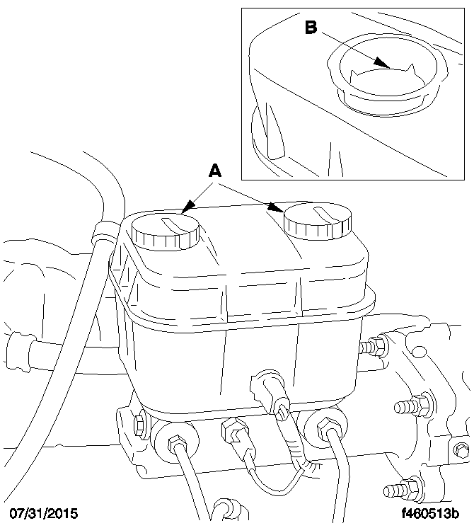
- A. Open caps and check fluid level.
- B. Fill to this level.
Fig. 12.3, Main Cylinder Reservoir
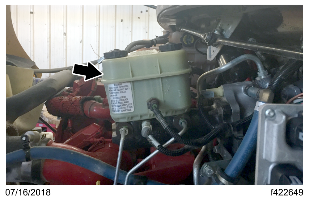
Due to the mounting angle of the main cylinder on some vehicles, it is not possible to fill the back reservoir up to the bottom of the fill-neck. For these vehicles, fill only the front main cylinder reservoir up to the bottom of the fill-neck.
Fig. 12.4, Main Cylinder Reservoir, Alternate Mounting Angle
Meritor Cam-Main® Q Plus Brakes
Cam-Main brakes are air-actuated, cam-operated, foundation brakes. The Q Plus increases service life and mileage between relines by providing more lining thickness. A specially designed S-cam and heavy-duty shoe return spring allow additional shoe travel required to fully wear the thicker lining blocks. An improved camshaft bushing contributes to longer service life.
Cam-Main Q Plus Operation
When the brake pedal is depressed, compressed air enters the brake chamber, causing the diaphragm to move a pushrod assembly.
The pushrod turns the slack adjuster and brake camshaft. As the camshaft turns, the S-type cam head forces the brake shoes against the brake drum and braking occurs.
When the brakes are released and air is exhausted from the brake chamber, the actuator return spring (within the brake chamber) and the brake shoe return spring return the camshaft, brake shoes, slack adjuster, and pushrod to their released positions.
Meritor WABCO® Pneumatic Antilock Braking System (ABS)
Pneumatic ABS is an electronic wheel speed monitoring and control system that works with the air brake system. It passively monitors vehicle wheel speed at all times, but controls wheel speed during an emergency or reduced-traction stop. In normal braking applications, the standard air brake system is in effect.
Pneumatic ABS Operation
The Meritor WABCO ABS is a four-sensor system. It combines one front-axle control channel with one rear-axle control channel to form one control circuit.
Example: The sensor and solenoid control valve at the left front wheel form a control circuit with the sensor and solenoid valve at the right rear axle.
ABS includes signal-generating tone wheels and sensors located in the wheel hubs of each sensed axle. The sensors transmit vehicle wheel speed information to an electronic control unit.
IMPORTANT: For proper ABS operation, do not change tire sizes. The sizes of the tires installed during production are programmed into the electronic control unit. Installing different sized tires could result in a reduced braking force, leading to longer stopping distances.
During emergency or reduced traction stops, fully depress the brake pedal until the vehicle comes to a safe stop. Do not pump the brake pedal. With the brake pedal fully depressed, the ABS will control all wheels to provide steering control and a reduced braking distance.
Although the ABS improves vehicle control during emergency braking situations, the driver still has the responsibility to change driving styles depending on the existing traffic and road conditions. For example, the ABS cannot prevent an accident if the driver is speeding or following too closely on slippery road surfaces.
Even if the ABS is partially or completely inoperative, normal braking ability is usually maintained.
IMPORTANT: If a solenoid control valve (or combination solenoid control valve) is damaged and inoperative, normal braking may be impaired.
Automatic Slack Adjusters
NOTICE
Automatic slack adjusters should never be manually adjusted except during routine maintenance of the foundation brakes (e.g., replacing shoes), during slack adjuster installation, or in an emergency situation.
When the brake pushrod stroke exceeds the legal brake adjustment limit on a vehicle, there is likely a mechanical problem with the foundation brake components or the adjuster is improperly installed.
Visit a repair facility as soon as possible when brakes equipped with automatic slack adjusters are determined to be out of adjustment.
Automatic Traction Control
Vehicles with electronic engines and ABS may have Automatic Traction Control (ATC). On these vehicles, the ATC system automatically limits wheel spin during reduced-traction situations. In normal braking applications, the standard air brake system is in effect.
During reduced-traction situations, the ATC solenoid valve controls air pressure to the modulator valves and they in turn increase, hold, or reduce pressure to the appropriate brake chambers to provide better traction whenever wheel spin occurs.
When the ATC system is in the NORMAL mode, it will apply gentle braking to the spinning wheel, to improve power to the wheel(s) with better traction. If both wheels are spinning, the system will signal the engine to reduce power.
ATC may include a deep snow and mud option to increase available traction on extra soft surfaces like snow, mud, or gravel. If so equipped, a momentary contact rocker switch labeled ATC will be located on the dash. Pressing the switch will temporarily allow more wheel spin. The activation of the deep snow and mud option is indicated by a flashing WHEEL SPIN lamp. Pressing the switch again will cycle the system back to normal operation.
NOTICE
After the ignition switch is turned on, the ABS indicator light and the WHEEL SPIN indicator light illuminate for about three seconds. After three seconds, the warning lights go out if all of the ABS components are working.
During vehicle operation, solid illumination of the ABS light indicates a problem with the vehicle ABS. Repair the ABS immediately to ensure full braking capability.
If equipped with ATC, an amber WHEEL SPIN indicator light illuminates if one of the drive wheels spins during acceleration. When the light illuminates, partially release the throttle pedal to stop the spinning wheel. The light goes out when the wheel stops spinning.
If slippery road conditions continue, turn on the differential lock switch. See Chapter 11 for axle switch instructions.
NOTICE
Electronic Stability Control
Electronic Stability Control (ESC) automatically reduces engine power, applies the engine brake (if so equipped), and/or applies the brakes when the acceleration sensor detects that the vehicle is at risk of rolling over. In addition, ESC offers the added capability of complete directional stability (yaw control) in oversteer and understeer conditions to reduce the likelihood of drift-out. The system determines where the driver is attempting to steer the vehicle and how much brake demand is required in order to more precisely control the vehicle in an emergency situation.
ESC works by constantly comparing the driver’s intention with the vehicle's actual behavior. The system does this by monitoring systems such as wheel speed, steering angle, yaw rate, lateral acceleration, throttle position, and brake application. A central microcomputer analyzes the collected data and triggers a response to keep the vehicle on course when an unstable condition is detected.
The roll stability control system automatically reduces engine power, applies the engine brake (if so equipped), and/or applies the brakes when the acceleration sensor detects that the vehicle is at risk of rolling over. The control can intervene even before an advisory message is displayed.
When the system detects that the vehicle is at risk of oversteering or understeering, it applies individual wheel end brakes, activates the engine brake (if so equipped), and/or cuts engine power, depending on the severity. As a result, the driver has full control over the vehicle until the system detects a potential risk and intervenes accordingly. ESC operates automatically; the driver does not monitor or activate the system. When ESC activates, an indicator lamp illuminates on the instrument panel. See Fig. 12.5 for the indicator lamp used on the ICU3 instrument panel and Fig. 12.6 for the indicator lamp used on the Ametek instrument panel.

Fig. 12.5, ESC Indicator Lamp, ICU3 Panel
Fig. 12.6, ESC Indicator Lamp, Ametek Panel
Exhaust Brake
General Information
An exhaust brake is an optional auxiliary braking system that assists, but does not replace, the service brake system. The driver can use the exhaust brake, in combination with the accelerator and clutch pedal (if so equipped), to make maximum use of the exhaust brake in off-highway and mountain driving as well as in traffic or high-speed highway driving.
The exhaust brake is controlled by a dash-mounted rocker switch, shown in Fig. 12.7 , to help slow the vehicle when the accelerator is released.
To turn the exhaust brake on, press on the upper part of the rocker switch. When the exhaust brake switch is on, an amber light emitting diode (LED) illuminates inside the switch. When the panel lights are on, the EXHST BRK legend is backlit in green.
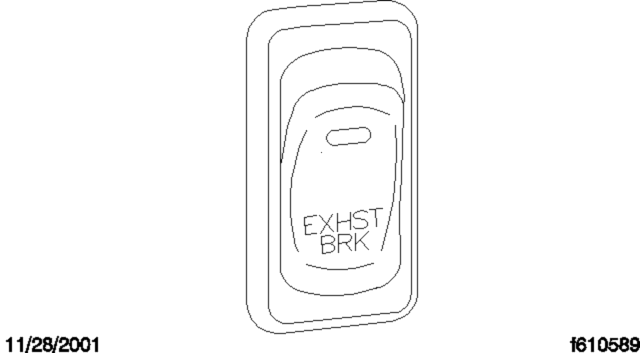
Fig. 12.7, Exhaust Brake Switch
The exhaust brake is only active when engine speed is between 1100 and 2700 rpm. Depressing the accelerator deactivates the exhaust brake. The ABS system, when active, also deactivates the exhaust brake.
The exhaust brake is a butterfly valve mounted in the exhaust pipe. When the driver's foot is not on the accelerator pedal and the upper half of the exhaust brake switch is pressed in, with the amber light on the switch illuminated, an air cylinder shuts the butterfly valve, which restricts the flow of exhaust gases and retards the engine. This retarding action is carried through the engine and drivetrain, slowing the vehicle and reducing the need for frequent service brake applications.
Exhaust brakes are not intended for use as the primary braking system during vehicle operation.
Starting the Engine
Before starting the engine, make sure that the lower half of the exhaust brake switch is pressed in and the amber light is not illuminated. Do not turn the exhaust brake on until the engine has reached normal operating temperatures.
Operating Characteristics
When you remove your foot from the accelerator, and the upper half of the exhaust brake switch is pressed in with the amber LED illuminated, the exhaust brake is applied. The following conditions should exist if the brake is operating properly:
A slight change in the sound of the engine may be noticed when the exhaust brake is applied.
Exhaust smoke should appear as normal.
Engine temperature should remain in the normal operating range.
Road speed usually decreases when the exhaust brake is applied during a descent. When the vehicle is carrying a heavy load or the grade is extremely steep, the driver may need to apply the service brakes occasionally.
Do not expect a retarding effect similar to sudden hard application of the service brakes. The exhaust brake retards the vehicle with a smooth braking effect.
During a descent, the tachometer usually shows a drop in rpm depending on the grade and the vehicle load.
Depending on the grade and vehicle load, you may or may not feel the retarding force acting against your body when the brake is applied. The retarding force of the brake may not always be noticed, but it is actually preventing the vehicle from going much faster.
Driving Downhill
While approaching a steep grade, make sure that the upper half of the exhaust brake switch is pressed in, with the amber LED illuminated. The exhaust brake comes on as soon as you remove your foot from the accelerator pedal. While going down the grade, use a low enough gear to safely descend with a minimum application of the service brakes. As a general guideline, use the same gear as you would to ascend the hill.
NOTICE
Apply the service brakes to reduce the engine rpm or make a slower descent by using a lower gear.
Shutting Down the Engine
Make sure the exhaust brake switch is turned off before shutting down the engine.
Brake Burnishing (new vehicle)
IMPORTANT: Check the brake system and ensure that it is in proper operating condition before attempting the brake burnishing procedure.
1.
In a safe area, make 10 sharp brake applications or "snubs," slowing the vehicle from 40 to 20 mph (64 to 32 km/h) using light (approximately 10 to 20 psi [69 to 138 kPa]) brake pressure.
2.
Make 10 stops from 20 mph (32 km/h) using moderate (20 to 30 psi [138 to 207 kPa]) brake pressure.
3.
Make 2 stops from 20 mph (32 km/h) using hard (full application of air pressure) brake applications.
NOTE: After the hard brake applications, it is normal to notice a hot brake odor.
4.
Drive the vehicle 5 to 7 miles (8 to 11 km) allowing the brakes to cool, and then come to a stop.
NOTE: After performing the burnishing procedure, there should be no brake noise and the brakes should have good stopping ability.
5.
If the brakes pull the vehicle to one side or grab after the burnishing procedure, contact a Freightliner dealer for assistance.
Bendix Intellipark™ Park Brake System
General Information
The following information provides steps to perform an air brake test for vehicles equipped with the Bendix Intellipark park brake system. The park brake switch has two light emitting diodes (LEDs). See Fig. 12.2 . Both LEDs illuminate when the parking brake is set; the LEDs are extinguished when the parking brake is released.
For electric powered vehicles, turn the ignition key to the ON position. This keeps the high-voltage system from operating. To start the high-voltage system, turn the ignition key to the start position and release.
IMPORTANT: Before performing any of the following tests, chock the tires to prevent the vehicle from moving.
Static Air Leakage Test
NOTE: Ensure that the air brake system is fully charged before performing the following steps.
1.
Turn the ignition key to the ON position (the engine is off, or the high-voltage system is disengaged for an electric vehicle).
2.
Release the parking brake and remove your foot from the brake pedal.
3.
Press the throttle pedal and hold it there.
4.
Observe the air gauges and time the air pressure loss. After the initial stabilization of the air pressure, the loss rate should be no more than 2 psi (14 kPa) per minute.
5.
Set the parking brake for the remainder of the tests.
Service Brake Air Leakage Test
1.
Turn the ignition key to the ON position (the engine is off, or the high-voltage system is disengaged for an electric vehicle).
2.
Depress the brake pedal continuously for several minutes.
3.
Observe the air gauges and time the air pressure loss. After the initial loss of air pressure, the loss rate should be no more than 3 psi (21 kPa) per minute.
Low Air Warning System Check
1.
Turn the ignition key to the ON position (the engine is off, or the high-voltage system is disengaged for an electric vehicle).
2.
Depress the brake pedal repeatedly to release air pressure from the brake system.
3.
When the air pressure drops below the preset level, the emergency buzzer activates, the low air brake pressure warning lamp illuminates, and the LEDs on the Intellipark parking brake control valve flash off and on.
Spring Brake Valve Test
1.
Turn the ignition key to the ON position (the engine is off, or the high-voltage system is disengaged for an electric vehicle).
2.
Depress the brake pedal repeatedly to release air pressure from the brake system.
3.
Observe the Intellipark parking brake control valve shown in Fig. 12.2 . When the parking brake is set, the top LED changes from flashing to solid.
Air Pressure Recovery Check
1.
Turn the ignition to the start position to start the engine or electric motor.
2.
With the transmission in neutral, increase the engine idle speed.
3.
Observe the air pressure gauges and measure the time it takes to build pressure from 85 to 100 psi (586 to 690 kPa). This should occur within 45 seconds.
Governor Cut Out Check
With the drivetrain running or the high-voltage system engaged, observe that the governor cut out pressure is between 120 to 130 psi (827 to 896 kPa).
Governor Cut In Check
With the drivetrain running or the high-voltage system engaged, depress the brake pedal several times to reduce the air pressure between 90 to 100 psi (621 to 690 kPa).
Spring Brake Test
IMPORTANT: This test is performed differently depending on the type of drivetrain installed on the vehicle. Ensure that the test is completed in a safe location away from other vehicles.
Engine Powered Vehicles
1.
With the engine running and the parking brake engaged, remove the chocks from the tires.
2.
Shift the transmission into drive and gently pull against the parking brake to test the hold strength.
Electric Powered Vehicles
1.
With the high-voltage system and the parking brake engaged, remove the chocks from the tires.
2.
Depress the brake pedal and hold.
3.
Release the parking brake control valve. The LEDs on the control valve will extinguish.
4.
Shift the transmission into drive and slowly move forward at 3 to 5 mph (5 to 8 km/h).
5.
With the vehicle moving, engage the parking brake. The LEDs will activate on the parking brake control valve and the vehicle should stop.
Service Brake Test
IMPORTANT: This test is performed differently depending on the type of drivetrain installed on the vehicle. Ensure that the test is completed in a safe location away from other vehicles.
1.
With the drivetrain running or the high-voltage system engaged, wait for normal air pressure to build in the brake system, then depress the brake pedal and release the parking brake.
2.
Shift the transmission into drive and move forward at 5 mph (8 km/h).
3.
Firmly depress the brake pedal.
4.
Note any pulling to one side, unusual feel, or delayed stopping action.