Electric Vehicle
Electric Vehicle System Overview
NOTE: The information provided in this chapter is specific to the electric vehicle. Chapters in this manual other than the engine and transmission chapters also apply to the electric vehicle.
DANGER
The Saf-T-Liner C2 Electric Vehicle is powered by two batteries, and is a direct drive system with a two-speed transmission; there are no additional transmission or torque coupling devices installed on the vehicle. The motor torque and energy management strategy are controlled by the vehicle control unit (VCU) to maximize the overall efficiency and performance of the vehicle.
Safety Information
DANGER
Warning labels are attached to high-voltage vehicle components. Some examples are shown in Fig. 18.1 . Do not attempt any type of work on these components unless you have completed HV3 Daimler Safety Training.

Fig. 18.1, High-Voltage Warning Labels
Regenerative Braking
This vehicle is equipped with a regenerative braking system. When the accelerator pedal is released, the electric motor acts as a generator in order to slow down the vehicle, while at the same time, send energy back into the batteries. When the brake pedal is depressed, regenerative braking is automatically blended with the mechanical braking.
The regeneration will feel as if the brake is being lightly applied when the driver removes their foot from the accelerator pedal. The full power of the service brake is always available to the driver, and regenerative braking is automatically shut off during an antilock brake system (ABS) event.
Tire Replacement
IMPORTANT: When replacing tires, the replacement tires revolutions per mile (RPM) must match the RPM of the original tires installed on the vehicle. This maintains the propulsion drive safety check performed by the drivetrain electronic control unit (ECU). It compares vehicle speed, drive motor (traction) speed, and antilock brake system (ABS) wheel sensor speed. If tires are mounted that differ from the factory RPM, the drivetrain ECU will detect an 'uncontrolled acceleration' event and disable the forward propulsion by shifting the transmission into neutral. Shutting down the vehicle and restarting the system will temporarily clear the fault.
Charging the Vehicle Batteries
IMPORTANT: The following battery charging instructions are used with the Proterra battery charging dispenser. If another battery charging dispenser is used, refer to the manufacturer's instructions to charge the vehicle batteries.
Perform the following steps to charge the vehicle batteries.
1.
Park the vehicle near the charging dispenser, turn the ignition key to the OFF position, and set the parking brake.
NOTE: The battery disconnect switch is located inside the battery box on the side-wall.
2.
Ensure that the battery disconnect switch is in the ON position. The disconnect switch must be in the ON position in order to charge the batteries.
3.
Open the charge port door, located behind the entrance door. See Fig. 18.2 .
NOTICE
4.
Open the upper charge port cover first, then open the lower charge port cover. See Fig. 18.2 , items 2 and 3.
5.
Plug the power feed connector into the charge port. Push hard until a 'click' sound is made. See Fig. 18.3 .

- 1. Charge Port
- 2. Lower Charge Port Cover
- 3. Upper Charge Port Cover
- 4. End Charge Button - press when charging is complete.
- 5. Red LED - indicates a problem with the charger connection.
- 6. Green LED - flashes when charging; remains solid when charging is complete.
- 7. Charge Port Door
Fig. 18.2, Vehicle Charge Port

- 1. Power Feed Connector
- 2. Charge Port
Fig. 18.3, Plugging the Power Feed Connector into the Charge Port
6.
The green light above the charge port will begin to flash, indicating the batteries are being charged.
6.
The charger connected indicator on the instrument panel illuminates during charging. It can take up to 10 seconds before the indicator illuminates.
7.
The charging dispenser has a lamp to indicate the charging status. See Table 20.1 .
|
Charging Dispenser Lamp Legend
|
|
|---|---|
|
Lamp Color
|
Description
|
|
White
|
Available to charge the vehicle.
|
|
Green (communication)
|
Solid - charging dispenser is plugged up but not communicating with the vehicle.
|
|
Flashing - charging dispenser is communicating with the vehicle.
|
|
|
Blue (charging)
|
Flashing - batteries are being charged.
|
|
Solid - batteries charged to 100% capacity.
|
|
|
Red
|
Out of service.
|
Table 18.1, Charging Dispenser Lamp Legend
8.

- 1. Charge Dispenser Status Lamp
- 2 E-Stop Button (for emergency only)
- 3. End Charge Button
Fig. 18.4, Charging Dispenser
9.
After waiting 15 seconds, ensure that the green light above the charge port is flashing rapidly. Then press the release button to disconnect the power feed connector. See Fig. 18.5 .

- 1. Release Button
- 2. Charge Port
Fig. 18.5, Removing the Power Feed Connector
Motor Starting and Shutdown
Starting
NOTE: When the charger is plugged into the vehicle and the ignition is on, the charger connected indicator illuminates in the instrument panel. During this time, the transmission can not be shifted and the motor is not enabled.
1.
Disconnect the vehicle charging cable, if connected.
2.
Set the parking brake, if it is not already engaged. See Fig. 18.6 , item 1.
3.
Turn the key fully clockwise to the START position, shown in Fig. 18.6 , item 2, and hold for approximately one second, then release the key. Wait for the motion enabled indicator to blink.
3.
The motion enabled indicator blinks when the vehicle is started. A blinking indicator means the vehicle is not ready to be driven. When the vehicle is ready to drive, the indicator stops blinking and remains solid.

- 1. Park Brake
- 2. Ignition Switch
Fig. 18.6, Park Brake and Ignition Switch
4.
Apply the service brake, then release the parking brake.
5.
With the service brake applied, press the desired mode on the shift control to put the vehicle in gear, then slowly release the service brake.
Shutdown
1.
With the vehicle stopped, place the transmission in neutral (N).
2.
Set the parking brake.
3.
Turn the key to the OFF position.
4.
Remove the key from the ignition switch.
NOTE: When the key is removed from the ignition, the high voltage is shutoff, but the instrument panel may remain on for 60 seconds.
Cold Weather Starting, Air Compressor
IMPORTANT: When operating the vehicle in cold temperatures, the air compressor may require a longer time to start up. Upon vehicle start, if the air compressor did not start up normally, or air pressure does not increase after 60 seconds, perform the key cycling sequence below.
Follow the steps below to cycle the ignition switch on and off in extreme cold starting temperatures.
1.
Set the parking brake.
2.
Turn the ignition switch to the ON position.
3.
Wait for 60 seconds, listening for the air compressor to start up. Pump the brakes if necessary to deplete the air tanks.
4.
If the air compressor does not start, turn the ignition switch to the OFF position.
5.
Wait for 15-30 seconds and turn the ignition switch to the ON position.
6.
Repeat steps 2-5 until the air compressor starts. This may take up to four key cycles.
Transmission
The Electric Saf-T-Liner C2 School Bus is equipped with a Proterra two-speed automated transmission. A push-button shift selector is used by the driver to select the transmission ranges. See Fig. 18.7 . When a gear is selected, the letter for that gear appears in the gear display window.
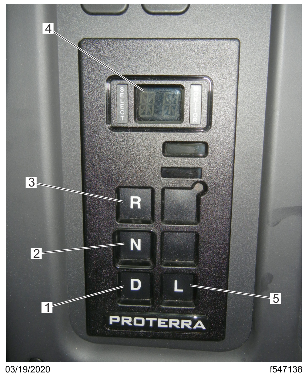
- 1. Drive (D) Button
- 2. Neutral (N) Button
- 3. Reverse (R) Button
- 4. Gear Display Window
- 5. Low (L) Gear Button
Fig. 18.7, Proterra Shift Selector
D (Drive)
The drive position selects the default start gear and automatically upshifts and downshifts. As the vehicle slows, the transmission will downshift automatically.
When going downhill, downshift to a lower transmission range to help maintain control of the vehicle. During downhill operation, the transmission may upshift to the next higher range, if the motor is exceeding its governed speed in the lower range.
N (Neutral)
The neutral position is used when starting the motor and for stationary operation.
When neutral is selected, the vehicle service brakes, parking brake, or emergency brake must be applied. Selecting neutral does not apply vehicle brakes unless an auxiliary system to apply the parking brake is installed.
Do not let the vehicle coast in neutral. If the vehicle is allowed to coast in neutral, the driver could lose control of the vehicle.
R (Reverse)
Always bring the vehicle to a complete stop before shifting from a forward range to reverse, or from reverse to a forward range. When the selector is in reverse, a warning signal will sound.
Do not idle in reverse for more than 5 minutes. Select N (neutral) when time at idle exceeds 5 minutes.
Low Gear (L)
Use low gear when pulling through mud or deep snow, when maneuvering in tight spaces, or when driving up or down very steep grades. Low gear provides the vehicle with its maximum driving torque.
Standard Instruments
Battery Charge Gauge
The battery charge gauge measures the level of battery power. A warning lamp illuminates when battery power is low. See Fig. 18.8 .
WARNING

- 1. Low Battery Warning Lamp
Fig. 18.8, Battery Charge Gauge
Battery Temperature Gauge
During normal operation, the battery temperature should register approximately in the middle of the gauge. See Fig. 18.9 . A warning lamp activates when battery temperature is above 120°F (49°C). The warning lamp deactivates when battery temperature is below 113°F (45°C).

- 1. Battery Temperature Warning Lamp
Fig. 18.9, Battery Temperature Gauge
Motor Temperature Gauge
NOTE: The motor icon under the gauge will never activate. Other motor warnings, such as the motor failure indicator, will activate in the instrument panel if a temperature issue causes motor failure.
During normal operation, the motor temperature should register approximately in the middle of the gauge. If the gauge registers high (H) and the motor failure indicator activates, the driver should safely pull off to the side of the road. See Fig. 18.10 .

Fig. 18.10, Motor Temperature Gauge
Primary and Secondary Air Pressure Gauges
WARNING
Air pressure gauges register the pressure in the primary and secondary air systems. Normal pressure with the motor running is 100 to 120 psi (690 to 827 kPa) in both systems. See Fig. 18.11 .

- 1. Low Primary Air Pressure Warning Lamp
- 2. Low Secondary Air Pressure Warning Lamp
Fig. 18.11, Air Pressure Gauges
Air pressure gauges are required on all vehicles with air brakes. A low-air-pressure warning lamp and buzzer, connected to both the primary and secondary systems, activate when air pressure in either system drops below a minimum pressure of 65 to 75 psi (448 to 517 kPa).
When the motor is started, the warning lamp and buzzer remain on until air pressure in both systems exceeds minimum pressure.
Speedometer
Speedometer
Three kinds of speedometer faces are available. The U.S. version of the speedometer registers speed in both miles per hour (mph) and kilometers per hour (km/h), with mph in larger numbers. See Fig. 18.12 , item 2.
The NAFTA version (not shown) of the speedometer face reverses this arrangement, with km/h in larger numbers. The metric-only version (not shown) shows km/h exclusively.
Ametek Instrument Panel
The following information describes the various warning and indicator lamps found in the Ametek instrument panel. See Fig. 18.12 for an example of the gauges and Fig. 18.13 for an example of the warning and indicator lamps. See Chapter 5 for additional information and instructions regarding the Ametek instrument panel. Some instrument panel menus and sub-menus are not available on the electric vehicle.

- 1. Battery Charge Gauge
- 2. Speedometer
- 3. Battery Temperature Gauge
- 4. Primary Air Pressure Gauge
- 5. Secondary Air Pressure Gauge
- 6. Motor Temperature Gauge
- 7. Driver Display Screen
- 8. Toggle Button, Down
- 9. Toggle Button, Right
Fig. 18.12, Ametek Instrument Panel, Electric Vehicle (gauges)

- 1. Maintenance Warning Lamp
- 2. Left-Turn Indicator
- 3. Charger Connected Indicator
- 4. Motor Warning Lamp
- 5. Motor Failure Indicator
- 6. Performance Derate Indicator
- 7. Motion Enabled Indicator
- 8. Battery Warning Lamp
- 9. ABS Warning
- 10. Tire Pressure Monitoring System Indicator
- 11. High Voltage Interlock Loop Indicator
- 12. Right-Turn Indicator
- 13. Battery Failure Lamp
- 14. Low Air Brake Pressure Warning
- 15. Traction Control Indicator
- 16. Fasten Seat Belt Warning
- 17. Headlight High-Beam Indicator
- 18. Parking Brake On Warning
- 19. Low State of Charge Indicator
- 20. Cruise Control Indicator
Fig. 18.13, Ametek Instrument Panel, Electric Vehicle (warning lamps)
The instrument cluster has an emergency buzzer that sounds when serious conditions that require immediate attention occur.
A description of the standard warning and indicator lamps are listed below alphabetically.
ABS Warning
The ABS indicator illuminates when there is a malfunction in the vehicle antilock brake system (ABS).
NOTE: For more information about this lamp and the ABS system, see Chapter 12 .
Battery Failure Lamp
The battery failure lamp illuminates when the battery pack and/or the charging/discharging management system has a failure and needs immediate attention. Vehicle motor derate will occur.
Battery Warning Lamp
The battery warning lamp notifies the driver that there is an issue with diagnostics.
Charger Connected Indicator
The charger connected indicator notifies the driver that the vehicle batteries are being charged.
Cruise Control Indicator
The cruise control indicator illuminates when the cruise control is activated.
Emergency Buzzer
The emergency buzzer sounds during the ignition sequence and whenever one of the following conditions exists:
The air pressure falls below the preset level, which is 65 psi (448 kPa).
The parking brake is set with the vehicle moving at a speed greater than 2 mph (3 km/h).
Fasten Seat Belt Warning
The fasten seat belt warning indicator (seat belt icon) illuminates for 3 seconds after the ignition switch is turned on.
When the motor is operating, if the driver's seat belt is unfastened and the park brake is not set, the seat belt warning indicator illuminates and a warning chime activates. The warning chime will remain active for 10 seconds. The warning indicator remains illuminated until the driver's seat belt is fastened.
Headlight High-Beam Indicator
The high-beam indicator (sideways beam icon) illuminates when the headlight high beams are on.
High Voltage Interlock Loop Indicator
The high voltage interlock loop indicator illuminates when an open circuit (when a high voltage cable is disconnected from its component, or a high voltage component enclosure is open) is detected on the high voltage interlock loop. Take the vehicle to an authorized Freightliner dealer for service.
Left-Turn Indicator
The left-turn indicator flashes on and off when the left-turn signal lights are flashing.
Both turn signal indicators flash when the hazard warning flasher is turned on.
Low Air Brake Pressure Warning
The low air brake pressure warning indicator and emergency buzzer activate when the motor is turned on if air pressure in the primary or secondary air reservoir is below 65 to 75 psi (448 to 517 kPa), and remain on until air pressure rises above that level in both reservoirs.
Low Coolant Warning
NOTICE
Low State of Charge Indicator
The low state of charge indicator notifies the driver that the vehicle batteries need to be charged.
Maintenance Warning Lamp
When the maintenance warning lamp illuminates, the message display center will alert the driver as follows:
Air Filter Reminder—the air filter requires checking or replacement.
Motion Enabled Indicator
The motion enabled indicator blinks when the vehicle is started. When the vehicle is ready to drive, the indicator stops blinking and remains solid.
Motor Failure Indicator
The motor failure indicator notifies the driver when the motor and/or powertrain management system has failed and needs immediate attention. Vehicle motor derate will occur. Take the vehicle to an authorized Freightliner dealer immediately for service.
Motor Warning Lamp
The motor warning lamp notifies the driver that there is an issue with diagnostics. The vehicle will need service soon.
Parking Brake On Warning
The parking brake on indicator activates when the parking brake is engaged.
If the vehicle is moving at a speed of 2 mph (3 km/h) or more, the emergency buzzer will sound until the parking brake is released.
Performance Derate Indicator
The performance derate indicator notifies the driver of a regenerative braking derate or a powertrain motor derate. If the indicator activates, the driver should safely pull off to the side of the road and have the vehicle serviced as soon as possible.
Right-Turn Indicator
The right-turn indicator flashes on and off when the right-turn signal lights are flashing.
Both turn signal indicators flash when the hazard warning flasher is turned on.
Tire Pressure Monitoring System Indicator
The tire pressure monitoring system indicator illuminates when the system detects an issue with one or more tires such as under or over pressure or over temperature. A warning message also appears in the driver display screen.
Traction Control Indicator
The traction control indicator illuminates when the wheels lose traction.
Jumpstarting
Jumpstarting electric vehicles is identical to diesel vehicles, which use the vehicle 12-volt battery system. See Chapter 16 for jumpstarting instructions.
High Voltage Battery Recycling and Disposal
The high voltage batteries used in this vehicle are eligible and recommended for recycling. Contact your local Thomas Built Buses dealer for high voltage battery recycling information. To find an authorized Thomas Built Buses dealer, refer tohttps://thomasbuiltbuses.com/bus-sales-and-support/find-a-dealer/.