Driver Assistance Features
OnGuard™ Collision Safety System
Meritor WABCO OnGuard is a forward-looking radar-based safety system. The system includes forward collision warning, adaptive cruise control (ACC), and collision mitigation.
OnGuard equipped vehicles have antilock brakes (ABS) and automatic traction control (ATC), and either roll stability control (RSC) or electronic stability control (ESC). These systems work together to enhance control of the vehicle. Depending on the situation, any of these features may apply throttle control, engine brakes, and/or service brakes, as needed.
The front-looking antenna assembly transmits radar signals to, and receives them back from, objects ahead of the vehicle. To be detected, vehicles must be within the radar field of view and provide a surface area that can reflect the radar. The distance, speed, and angle of the vehicle ahead is calculated, and the driver is warned of potentially dangerous situations. The system also warns of stationary objects to alert the driver of potential obstructions ahead in their lane.
WARNING
System Limitations
The OnGuard Collision Safety System may provide little or no warning of hazards such as pedestrians, animals, oncoming vehicles, or cross traffic.
OnGuard CMS only brakes for lead vehicles located directly in front of your vehicle, and does not operate when vehicle speed is less than 15 mph (25 km/h).
Due to these limitations, the system:
will not react and alert the operator to objects crossing in front of the vehicle or oncoming traffic;
should not be relied on to track lead vehicles when traveling through a severe curve in the road. Because of this, ACC is not recommended for use on winding roads;
will alert, but not actively brake, on stationary objects;
should not be relied upon to track smaller objects like motorcycles, mopeds, bicycles, or pedestrians;
should not be relied on to alert drivers to vehicles in an adjacent lane.
OnGuard Display Unit
The OnGuard system controls are located in the display unit. The display provides visual and audible warnings and messages, as well as verification of correct system operation and faults. Menu selections are made by pressing the up and down arrows, and the MODE button. See Fig. 5.1 .
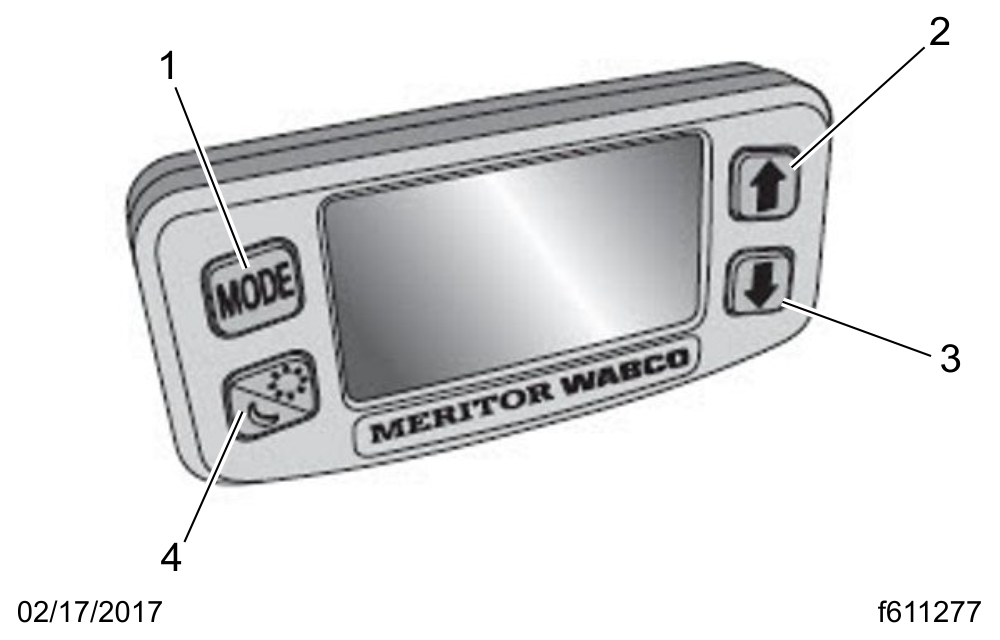
- 1. Mode
- 2. Day/Night Mode
- 3. Up
- 4. Down
Fig. 5.1, OnGuard Display Unit
The display includes:
an internal speaker
a graphic display
buttons to scroll and select options
day/night display mode
Collision Mitigation System (CMS)
The CMS provides the driver with audible and visual alerts when the vehicle's following distance could result in a rear-end collision. The OnGuard display unit shows a graphic of the condition, enhanced by a screen color relevant to the intensity of the situation. See Table 5.1 . If a potential rear-end collision is imminent, OnGuard's active braking automatically applies the engine and service brakes to slow the vehicle. The active braking application is intended only to provide early braking; the driver is still required to recognize and react to all driving situations.
IMPORTANT: CMS and active braking are not operational at vehicle speeds below 15 mph (25 km/h).
|
OnGuard Display Screen Background Colors
|
|
|---|---|
|
Screen Color
|
Description
|
|
Blue
|
General operation; no lead vehicles detected.
|
|
Green
|
Lead vehicle detected.
|
|
Yellow
|
Following distance alert, accompanied by an audible alert.
|
|
Red
|
Collision warning, stationary object warning. Accompanied with audible alert.
|
|
Amber
|
Data Error
|
Table 5.1, OnGuard Display Screen Background Colors
Standby
When no lead vehicle is detected, the display shows that the CMS is on and the radar is searching. See Fig. 5.2 .
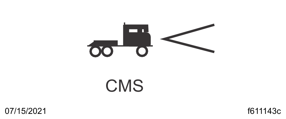
Fig. 5.2, CMS Standby (blue)
A Vehicle is Detected
When a lead vehicle is detected in the lane ahead, the display shows that the CMS is on and the radar is tracking a lead vehicle at the speed shown. See Fig. 5.3 .
If the following distance between the vehicle and the lead vehicle is too close, the CMS will emit an audible alert and the display background will turn yellow. The alert will end when the vehicle speed drops below the lead vehicle speed and the following distance is increased.
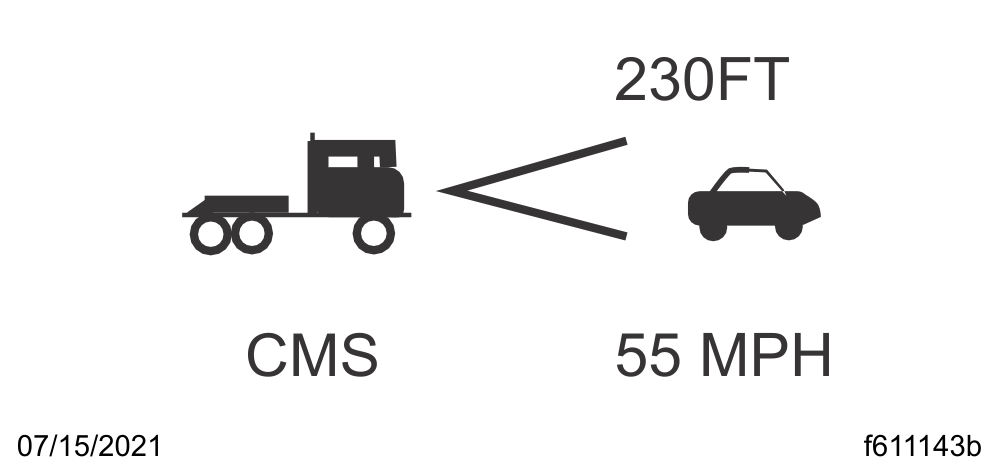
Fig. 5.3, CMS Lead Vehicle Detected (green)
Collision Warning
When a lead vehicle is detected traveling slower than your vehicle, or the gap between them becomes too close, the CMS warns of an impending collision by emitting an urgent audible alert and displaying the collision warning symbol with a red background. See Fig. 5.4 .
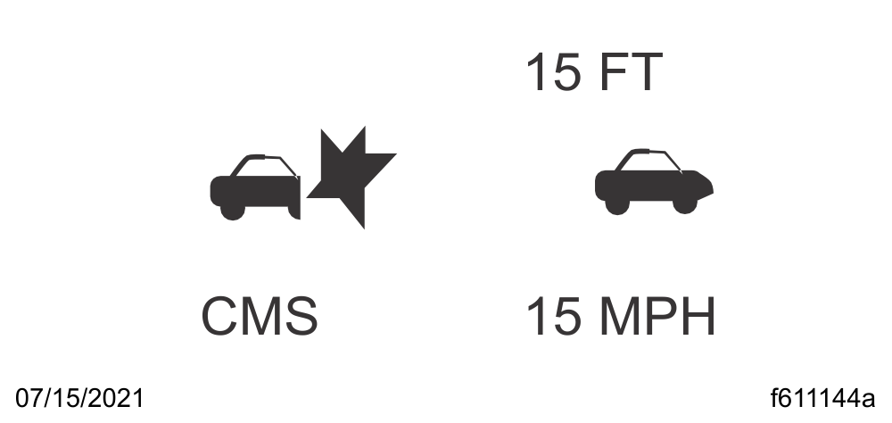
Fig. 5.4, CMS Collision Warning (red)
Adaptive Cruise Control (ACC)
ACC works in conjunction with conventional cruise control to maintain a minimum following distance when a lead vehicle is being tracked. The minimum following distance is maintained by automatically decelerating the vehicle using throttle, engine, and service brakes without driver intervention. When the lead vehicle is no longer being tracked, the set cruise control speed resumes automatically.
Standby
When no lead vehicle is detected, OnGuard ACC operates similarly to conventional cruise control. The cruise control set speed is shown on the OnGuard display unit. See Fig. 5.5 .

Fig. 5.5, ACC Standby (blue)
Lead Vehicle Detected
When a lead vehicle is detected in the lane ahead, the display shows that ACC is on and the radar is tracking it. See Fig. 5.6 .
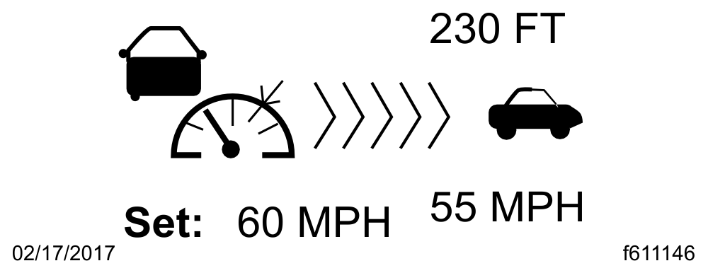
Fig. 5.6, ACC Lead Vehicle Detected (green)
If the driver uses the accelerator pedal to override the cruise control and approach a vehicle too closely, the ACC will emit an audible alert and the display background will turn yellow. The alert will end when vehicle speed drops below the lead vehicle's speed and the following distance is increased.
NOTE: The following distance alert does not operate at speeds below 15 mph (25 km/h).
Collision Warning
If the lead vehicle is traveling slower than the driver's vehicle, the CMS warns of an impending collision by emitting an urgent audible alert and displaying the collision warning symbol with a red background. See Fig. 5.7 .
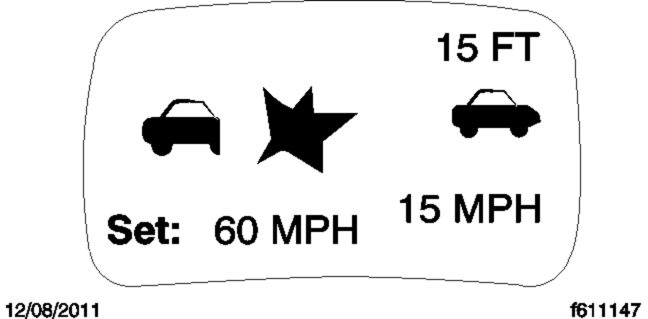
Fig. 5.7, ACC Collision Warning (red)
The braking control will activate and slow the vehicle. The driver must also initiate braking.
Error Screens
IMPORTANT: The OnGuard collision safety system is not operational when an error screen is displayed. If a fault occurs or OnGuard fails to properly track a vehicle, take the vehicle in for service as soon as possible. Standard cruise control will not function with an active OnGuard system fault.
If a system fault is detected, the OnGuard display unit will immediately display an error screen as shown in Fig. 5.8 . The first error code transmitted will be displayed first; additional faults (if any) can be viewed using the up or down buttons. The display does not show stored fault codes.
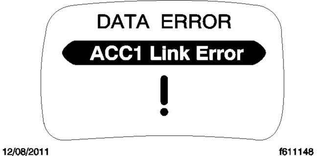
Fig. 5.8, OnGuard Error Screen (amber)
Refer to the OnGuard Collision Safety System Maintenance Manual MM-0951 for a full list of faults ( www.meritorwabco.com ).
Additional Features
Press the MODE button to access the OnGuard display unit additional features from the CMS or ACC main operating screen. Press the up and down arrows to scroll through each menu, then press the MODE button to select the value to be changed. In edit mode, press the up or down arrows to change a value setting, then press the MODE button to save the setting. Pressing MODE in each feature screen advances the display to the next feature.
The Display Control menu allows adjustment of the alarm volume, LCD brightness, LCD contrast, and U.S./metric unit conversion. See Fig. 5.9 .
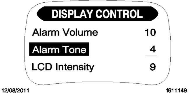
Fig. 5.9, Display Control Menu
The component test menu provides verification of system component operation and acts as a valuable OnGuard system diagnostic tool. The header will display either COMPONENT TEST or ACC FUNCTION , depending on the software release version of the OnGuard system. The component test screen shown in Fig. 5.10 provides access to the following components (press the up or down arrows to scroll through the menu):
brake pedal position
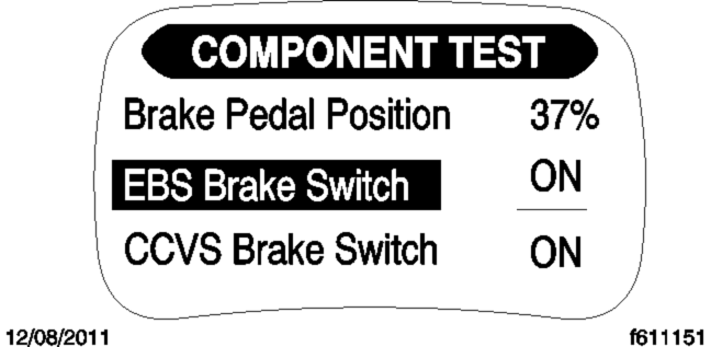
Fig. 5.10, Component Test Menu
EBS brake switch
CCVS brake switch
clutch switch
park brake switch
accelerator pedal position
driveline engaged
cruise control enable
cruise control set speed switch
cruise control coast switch
cruise control resume switch
cruise control accelerate switch
cruise control pause switch
Lane Departure Warning Controls
The lane departure warning system monitors the vehicle's position within the roadway lane markings and sounds a warning in the cab when the vehicle is about to stray outside its lane, provided the turn signal is not on and the vehicle is traveling at least 37 mph (60 km/h). The system includes a digital camera mounted high near the center of the windshield inside the cab and speakers that emit a sound similar to a rumble strip. The sound is made on the side of the vehicle it's straying toward, prompting the driver to respond and steer away from the sound and back into the center of the correct lane.
WARNING
The lane departure warning system powers up each time the ignition is turned to ON. The system conducts a self test, and initiates test tones from the left speaker and then the right speaker. Once the vehicle is started and the system is ready, the LED in the switch illuminates.
Press the LANE ALERT switch to temporarily disable the lane departure warning system. See Fig. 5.11 . Some vehicles are equipped with a timer that automatically re-enables the warning system after 15 minutes. On all other vehicles, the warning system will remain disabled until the driver enables the system by pressing the LANE ALERT switch again, or the ignition is cycled off and then on.
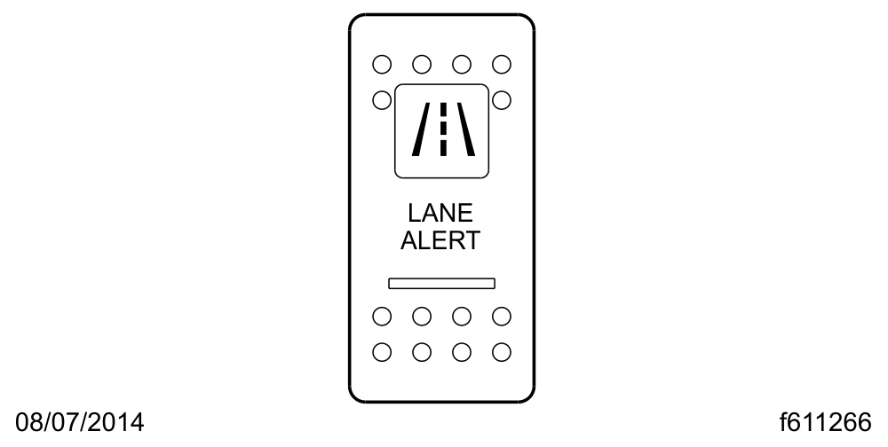
Fig. 5.11, Lane Departure Warning System Disable Switch
When the vehicle approaches the lane markings on either side, the system sense the activation of a turn signal. If a turn signal has not been activated, the system initiates the audible warning to alert the driver that the vehicle is departing its current lane of travel.
The LANE SRCHNG warning light illuminates to indicate the system is not fully functional. When the warning light is on, the system audible alert may not indicate a lane departure. Conditions that can cause the warning light to illuminate include:
The system is unable to detect lane markings.
Vehicle speed is less than 37 mph (60 km/h).
A system problem is detected.
OnLane™ Lane Departure Warning
WARNING
OnLane is a camera-based warning system that helps the driver avoid unintentional lane drifting.
The system utilizes a camera mounted near the top center of the vehicle windshield, which calculates vehicle position within the lane. When the vehicle crosses lane markings without the turn signal being activated, OnLane sounds an audible warning.
The Driver Alertness Warning (DAW) system provides a warning when weaving or erratic driving is detected within the driving lane.
System Startup
OnLane is activated when the vehicle ignition is turned on. Lane departure warnings are active only when the vehicle is traveling at 42 mph (68 kph) or above.
Intentional Lane Changes
The system identifies intentional lane changes by monitoring the turn signal, the brake switch, and vehicle speed. When a lane change is intentional, the assistance warnings are disabled. The following conditions will disable/enable the warnings:
If brake lights are ON, all warnings are disabled
If the Left Turn Signal is ON, left departure warnings are disabled
If the Right Turn Signal is ON, right departure warnings are disabled
If the vehicle’s speed is under 42 mph (68 kph), all warnings are disabled
If the hazard lights are ON, all warnings are enabled
Unintentional Lane Departure
The system constantly monitors and calculates the vehicle's position within the lane. In the event of an unintentional lane change, the system provides an audible warning (rumble strip noise). The audible warning will terminate once the vehicle is guided back into the lane.
Driver Alertness Warning
The system detects erratic driving based on weaving behavior within the driving lane. OnLane computes a "Driver Alertness Index" based on driving performance, and alerts the driver when it falls below a certain threshold. DAW warns the driver by providing an intermittent warning tone when it detects erratic driving or weaving within the driving lane. The alert terminates when driving performance improves, or when the key is cycled.
Temporarily Disabling the System
The system can be temporarily disabled by pressing the OnLane switch. This disables warnings for 15 minutes. Warnings can be enabled by pressing the OnLane switch again.
Roll Stability System
The roll stability system may include the roll stability advisor (RSA) only, or it may also include the roll stability control (RSC).
A decal ( Fig. 5.12 ) on the auxiliary dash panel, and an amber-colored dash indicator light ( Fig. 5.13 ), indicate that the vehicle is equipped with roll stability system components.
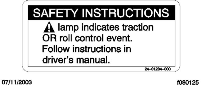
Fig. 5.12, Roll Stability Decal
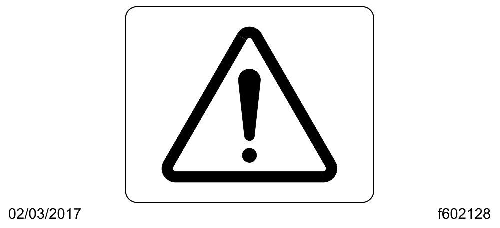
Fig. 5.13, Roll Stability Indicator Lamp
Roll Stability Advisor
IMPORTANT: This is not an advance warning system. The roll stability advisor displays a message only after the driving maneuver is completed.
The roll stability system uses a lateral-acceleration sensor that monitors rollover risk. Shortly after a curve, lane change, or other driving maneuver that results in a rollover-risk detection, a dash warning light illuminates, an audible tone sounds, and a driver advisory message is displayed in the driver message center. The purpose is to advise the driver that the previous maneuver produced a rollover risk.
The roll stability advisor displays different text messages depending on the severity of the risk of each occurrence of risky driving. From the highest risk level to the lowest risk level, the system will sound an audible alert, and display a message, as shown in Fig. 5.14 .
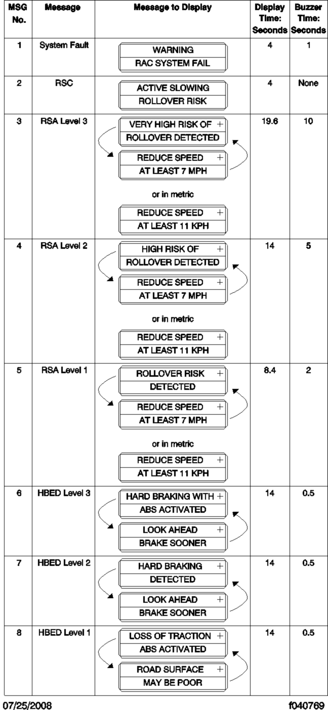
Fig. 5.14, Roll Stability and Hard-Braking Warnings
NOTE: The system will calculate and recommend a speed reduction value. It may be different than the values shown here.
Bring the vehicle to an authorized service facility if a system failure message is displayed.
Roll Stability Control
WARNING
The roll stability control system automatically reduces engine power, applies the engine brake, and/or applies the tractor and trailer brakes when the acceleration sensor detects that the vehicle is at risk of rolling over. The control can intervene even before an advisory message is displayed.
The dash indicator light illuminates whenever the roll stability control system intervenes.
Hard-Braking Advisor
The hard-braking advisor uses the information from the ABS wheel speed sensors to determine when braking is severe enough to produce lockup at one or more wheels on the tractor, and/or very rapid vehicle deceleration. Shortly after a hard-braking event occurs, an advisory message is displayed in the driver message center, indicating that the braking behavior was too aggressive for the current road surface conditions. This system is not a replacement for a driver's good judgment. Sometimes it is necessary to brake hard.
From the highest risk level to the lowest risk level, the system will sound an audible alert, and display a message, as shown in Fig. 5.14 .
Trip/Leg Totals
The driver message center records the number of messages received, and displays the number of messages as counts. Roll stability advisor (RSA) and hard-braking event data (HBED) counts can be viewed in the trip advisory screen, and the leg advisory screen.
Counts can be reset using the + key on the steering wheel. Clearing RSA and HBED leg counts will also reset the leg miles and leg hours. Clearing RSA and HBED trip counts will also reset trip miles, trip hours, leg miles, leg hours, and leg advisory counts. In addition, resetting leg miles will clear leg counts. Clearing trip miles will reset miles, hours, and counts in both the leg and trip screens.
The TRIP and LEG advisor screens count both the roll stability advisories (ROLL) and hard-braking events (BRK). For example, if during a TRIP, the driver message center recorded the events in Table 5.2 , the message center would display as shown in Fig. 5.15 .
|
RSA/HBED Count
|
|
|---|---|
|
Message Received
|
Message Counts
|
|
RSA Level 3
|
2
|
|
RSA Level 2
|
3
|
|
RSA Level 1
|
7
|
|
HBED Level 3
|
5
|
|
HBED Level 2
|
1
|
|
HBED Level 1
|
8
|
Table 5.2, RSA/HBED Count
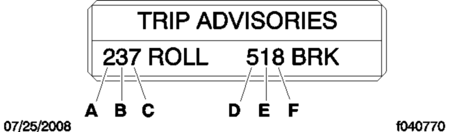
- A. RSA lev. 3 Count (2)
- B. RSA lev. 2 Count (3)
- C. RSA lev. 1 Count (7)
- D. HBED lev. 3 Count (5)
- E. HBED lev. 2 Count (1)
- F. HBED lev. 1 Count (8)
Fig. 5.15, Trip Advisor Message Screen
If the count reaches more than 9 occurrences an up-arrow symbol will appear, to indicate to the driver that the count has exceeded 9 counts. See Fig. 5.16 .
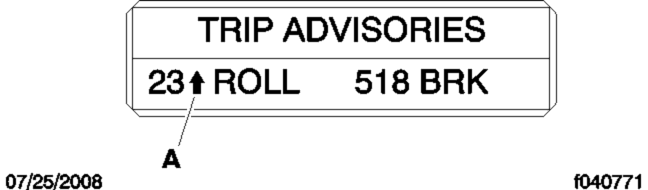
- A. RSA Lev. 1 has more than 9 counts.
Fig. 5.16, Trip Advisor Message Screen (more than 9 counts)
Enhanced Stability Control
WARNING
ESC offers the full capability of RSC (shown above) with the added capability of complete directional stability (yaw control) in oversteer and understeer conditions to reduce the likelihood of drift-out or jackknife. The system determines where the driver is attempting to steer the vehicle and how much brake demand is required in order to more precisely control the vehicle in an emergency situation.
ESC works by constantly comparing the driver input with the vehicle's actual behavior. The system does this by monitoring systems such as wheel speed, steering angle, yaw rate, lateral acceleration, throttle position, and brake application. A central microcomputer analyzes the collected data and triggers a response to keep the vehicle on course when an unstable condition is detected.
When the system detects that the vehicle is at risk of oversteering or understeering, it applies individual tractor wheel end brakes and trailer brakes, activates the engine retarder (if equipped), and/or cuts engine power, depending on the severity. As a result, the driver has full control over the vehicle until the system detects a potential risk and intervenes accordingly. ESC operates automatically; the driver does not monitor or activate the system.